CrystalFontz 632 and 634 with an Arduino
Years ago, I purchased a couple of CrystalFontz LCDs, the 634 and 632. Both are fantastic little devices that I’ve used on various projects. Recently, I’ve been looking to hook these up to an Arduino, and I finally got around to making it work. It wasn’t completely straightforward, so here’s how you can do it yourself.
These LCDs have two means of connecting: a standard DB9 (serial) connector (labeled J1 on the board and in the datasheet), and a set of through-holes you can solder wires to directly (labeled J2). In addition, the LCDs support SPI, though we won’t be needing that for our Arduino project.
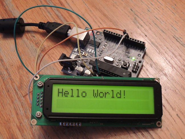
Here’s the finished product in action: an Arduino Duemilanove powering a CrystalFontz 632 LCD (though the 634 is just as easy to use as well):

Closing some jumpers
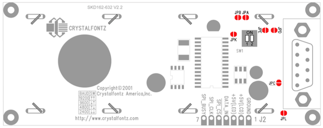
The most important part of getting the CrystalFontz LCDs to work with your Arduino is to remember to close two very important jumpers: JPB and JPE.

The two jumpers we’re interested in are located near the top right of the back of the LCD board.
Closing JPB
Looking in the datasheet, you’ll notice that the CrystalFontz LCDs assume an RS-232 compliant signal. This means that when you want to signify high, you send a negative voltage (typically -13V), and when you want to send low, you send a positive voltage (typically +13V).
Lucky for us, these CrystalFontz LCDs have the JPB jumper, which allows you to signify that your RS-232 data is inverted and coming from a UART-compatible microcontroller. This means that when you want to send high, you’ll send a positive voltage, and when you want to send low, you’ll send a negative voltage (we’ll actually send a 0 voltage, but more on that next).
Close the JPB jumper by carefully putting a little bit of solder between the two metal pads to form a connection.
Closing JPE
You’ll may remember that an Arduino only sends a max of +5V on it’s I/O pins. Further, as I pointed out in the previous section, the CrystalFontz LCD is assuming we’re going to be sending something much higher (typical RS-232 voltages are +13 and -13, which is helpful over long distances and with high interference).
Again, lucky for us, the CrystalFontz LCDs have a solution, in the form of the JPE jumper. Closing this jumper (along with JPB, above) informs the LCD that we’re going to be sending +5V for high and 0V for low.
Close JPE by again putting just enough solder between the two metal pads to connect the them together.
After closing the jumpers, be sure to check out the SparkFun writeup on the difference between RS-232 and TTL data.
Setting DIP switches for baud rate
One quick thing to note: on the back of the board you’ll notice a pair of DIP switches. Be sure to set these for 9600 baud (left one down, right one up). You should see a diagram in the bottom left of the board for each combination.
The Arudino code we’ll be writing assumes 9600 baud, but you can experiment with different speeds.
Wiring it up
Flip the LCD over to look at the back and locate the J2 connector. It has a set of pins labeled like the following:

You can solder wires directly to these tabs, or (as I did) solder on some female headers so you can quickly add and remove jumper wires.

Next up, wire the GROUND to the Arduino’s GND, +5V(LCD) to the Arduino’s 5V pin, and the DATA_IN to pin 7 (doesn’t matter which pin, so long as it’s not 0 or 1, which are used as part of the serial connection to your computer).
A note on power requirements
Using the configuration above, the datasheet shows that the LCD won’t pull more than 9mA of current. However, you’ll notice there is a +5V(LED) connection. Applying 5V to this will turn on the backlight for the LCD, however (and this is important) the datasheet for the 632 shows that the maximum current draw with the backlight on is 380mA.
The Arduino, when powered by USB or a wall-wart, is capable of supplying this current, but it’s pushing it (I’m using a Duemilanove which appears to have a DC regulator capable of up to 800mA). You should be able to power the backlight off the Arduino, but you’re approaching the limits, and you certainly want to be careful about adding anything else to this current draw (LEDs, sensors, etc). You’ll probably want to consider using an external power source to power the LCD with the backlight on rather than drawing off the Arduino.
Writing the Arudino Sketch
Now that the LCD has the JPB and JPE jumpers closed and we’ve properly wired it up to the Arudino, let’s write a simple sketch to test it out.
Here’s a simple implementation that prints out “Hello World” on the LCD.
1 2 3 4 5 6 7 8 9 10 11 12 13 14 15 16 17 18 19 20 21 22 23 24 25 26 27 28 29 30 31 32 33 34 35 36 37 38 39 40 | |
A few things to note.
I’m using the built-in
SoftwareSeriallibrary to send RS-232 formatted data to the LCD. However, the LCD can only receive data (never transmit back to the Arduino), so we don’t actually care about setting a meaningful RX pin when setting up the LCD serial connection. Thus, I’m using pin 0.When the Arduino boots, it will turn on the backlight in the
setupfunction by sending +5V to pin 6 via theenableBacklight()method. Feel free to play with this using thedisableBacklight()method.At boot, I tell the LCD to clear the display and then draw the string “Hello World!”. These LCDs work by telling them what to display, and they will continue to display that message until you tell them to display something different (or shut off the power). Thus, the
loop()method does nothing, and actually just puts the Arduino into a low-power sleep for 1 second before doing it again.
Wrapping Up
And here’s what the finished product looks like!

These are great little LCDs that have lasted me years (and are still going strong). Looking forward to working them into my current projects.
Aside… Ye Olde MP3 Car
I mentioned earlier that I had purchased these LCDs years ago. Want to know what I originally intended them for? Why, an MP3 audio player for my car, of course!
Remember, this was before the introduction of the iPod. At the time, your options for playing music files that weren’t on just a linear audio CD were:
- an mp3 CD player (a device that looked like a typical portable CD player but would read specially formatted 640mb CDs formatted for Windows containing mp3 files),
- a mini-disc player, which was actually quite a cool idea (I had a second-hand Sony one), but were cumbersome to record with, or
- a full-blown computer with a hard drive!
Of course, I tried almost all of these before building my own DOS-based mp3 player. It was a motherboard I mounted on a cork trivet I “borrowed” from my mom, hooked up to a 10gb 5400 rpm hard drive, and powered by a dc-ac inverter.
I controlled everything using an RF remote control, and played my tunes over a home speaker system I placed strategically around the car. I connected my CrystalFontz 634 up, using the serial connector, to the computer, outputting the track I was playing along with cool-looking equalizers.
It all worked great until all the vibrations, bumps in the road, and other stressors destroyed the spinning hard drive platters. Before I could come up with a suitable replacement the iPod was introduced and the golden days of DOS-based car-mounted music machines like this were over.
